The stock sensor has an “IDLE VOLTAGE” stamped on the back which the sensor needs to be “SET” at in order to work properly and not set any DTC codes.
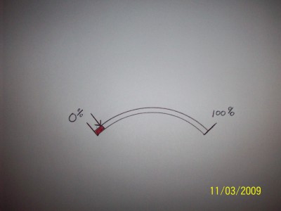
My replacement sensor is designed a bit differently only in the “IDLE VOLTAGE” portion of it. Look at the drawing and take notice to the area shaded in red. The first few degrees of movement in the beginning is the “IDLE VOLTAGE”. The voltage stays constant (does not rise). The end of the red shaded area is the point at which voltage rises, thus engine RPM’s increase.
When you install the replacement sensor you want to adjust the idle stop screw to find the point at which voltage begins to rise. (That would be the end of the red shaded area) The arrow indicates where I want you to set it, just a hair before the point voltage begins to rise. You could indeed bolt the sensor on and go. The result would be a little bit of pedal movement in the beginning that the engine wouldn’t respond, like free play let’s call it. NO “check engine “ light will occur if the adjustment is not made.